1 About your system
Dad built this controller himself. It does two jobs automatically:
- It runs the attic fan, using the attic and outside temperatures.
- It runs the grid charger for battery bank 4 overnight when the batteries are low.
It also monitors the house. It measures current to the furnace, air conditioner, dryer, lights, solar (Renogy) and batteries, and it estimates electricity and gas costs. It shows this on a homemade thermostat and sends a line of data over USB every hour.
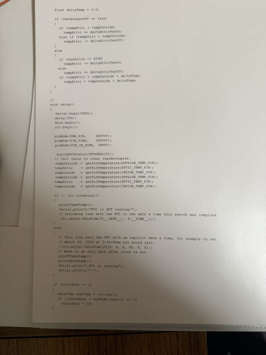
The program on the board is Dad's own, kept exactly as he compiled it. Its source code has not been found, so everything in this manual was worked out by reading the compiled program and watching the system run. Where something is not known for certain, the manual says so.
2 Parts and where they are
| Part | What it does |
|---|---|
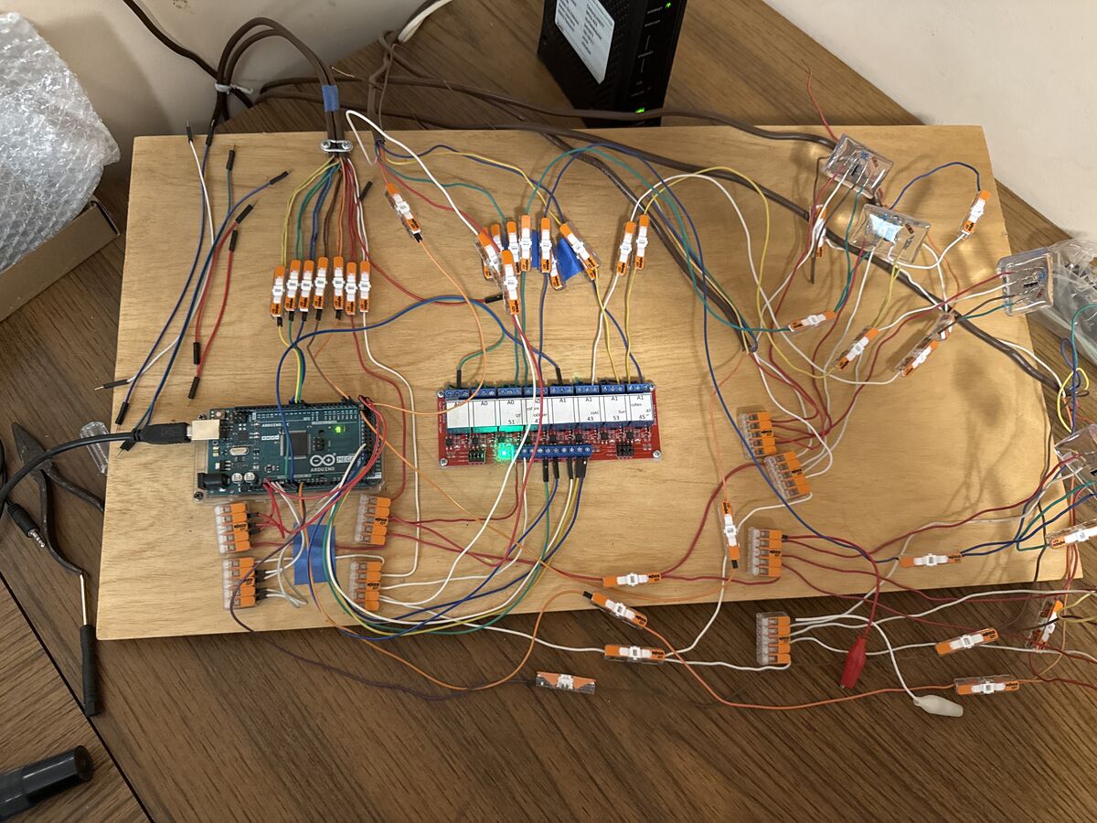
| Controller board | A wooden board holding the Arduino Mega 2560, the relay board and the sensor wiring. The Arduino's USB cable is its power supply and where the log comes out. |
| Arduino Mega 2560 | The computer that runs Dad's program. |
| Relay board | Switches which sensor the Arduino is reading at a given moment. Two more outputs switch the attic fan and the battery charger. |
| Thermostat | A 16×2 blue LCD and three push buttons fitted into an old Honeywell case, in another room. It is connected by the long brown cable. |
| Current sensors | Clamp-on sensors on the mains and on individual circuits (AC, furnace, dryer, lights, battery charger). |
| Temperature and light sensors | Attic temperature, outside temperature and a light sensor that measures sunlight. |
3 Using the thermostat
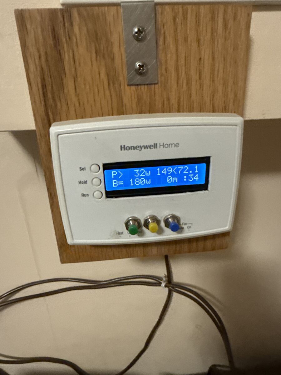
The display
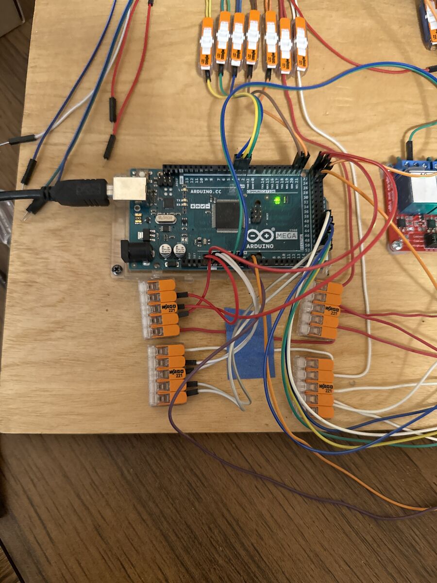
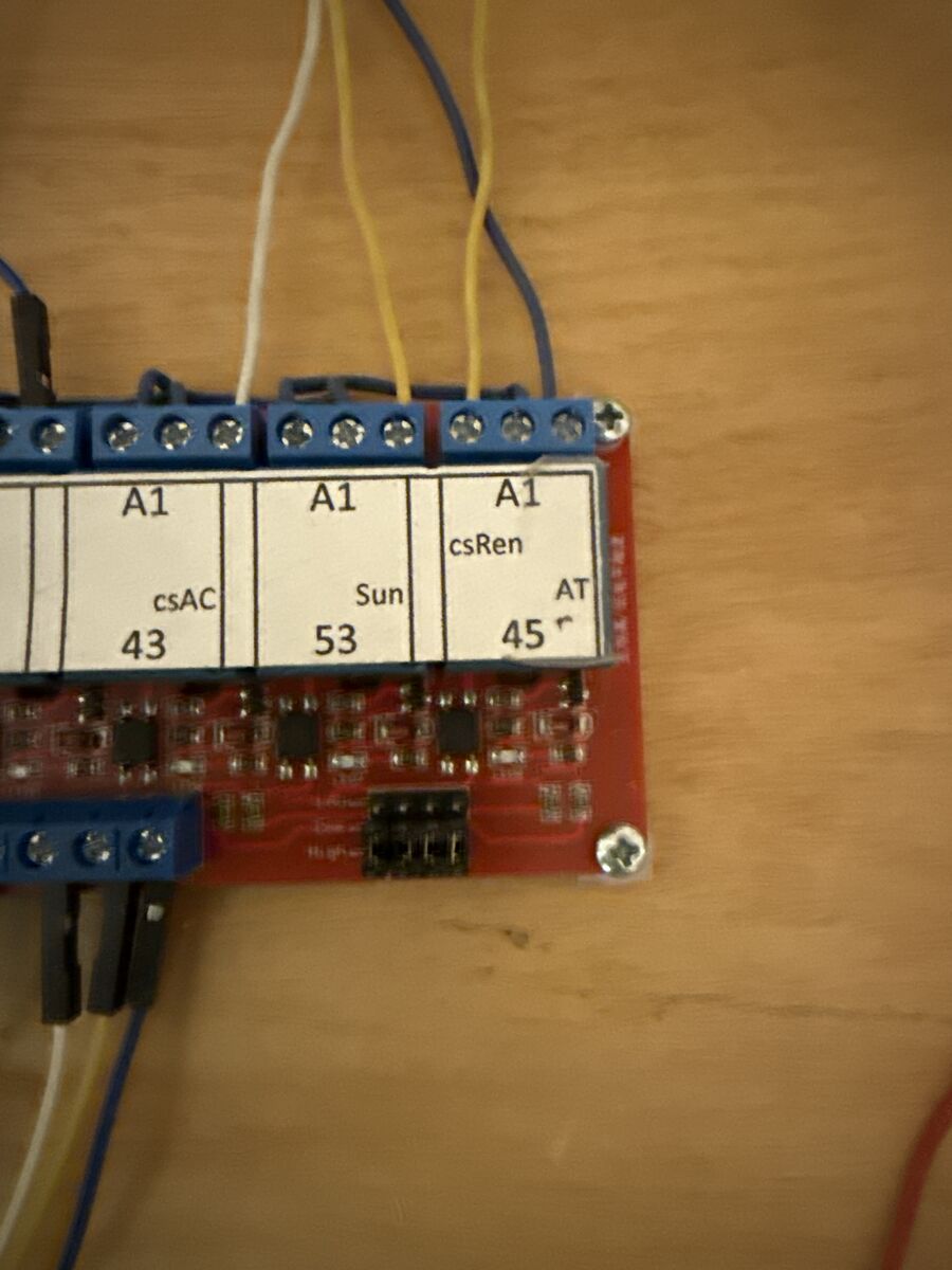
The display has two lines of 16 characters and refreshes several times a second. It has 9 screens. They show readings such as power in watts, temperatures, minutes running, and the state of the AC, heat, dryer and Renogy solar.
The exact meaning of every field on every screen has not been worked out yet. The photo shows one screen as an example.
The buttons
The three round buttons under the display are <, ^ and >. When you press one, its symbol appears briefly on the display. Use this to check which button is which.
| Button | Normally | While editing |
|---|---|---|
| < | Previous screen | Previous choice |
| ^ | Start editing the current screen | — |
| > | Next screen | Next choice |
Only screens 0, 1 and 4 can be edited. Screen 0 is the one you will use: it sets the attic fan mode (see Attic fan).
4 Attic fan
The attic fan has five modes:
| Display | Mode | The fan runs when… | Use it in |
|---|---|---|---|
off | Off | never | — |
on | On | always | — |
sum | Summer | the attic is above 90 °F | Summer: vents attic heat |
win | Winter | the attic is above 28 °F | Winter |
trk | Track | the attic is more than 5 °F warmer than outside | Spring and autumn |
To change the fan mode
- Press < or > until screen 0 is showing.
- Press ^ to start editing.
- Press < or > to step through the modes: off → on → sum → win → trk.
- Stop on the mode you want.
The mode is also printed in the log header as atticFan,off, atticFan,winter, and so on.
5 Battery charger
The controller switches the grid charger for battery bank 4 (relay output on pin 26). The charger runs only when both of these are true:
- The controller's clock is between 9 pm and 6 am, when off-peak electricity costs $0.05/kWh.
- The estimated battery charge is 50 % or less.
The charge level is an estimate, calculated from the measured currents. It is not measured directly. The estimate restarts at 72.25 % every time the controller powers up, whatever the real state of the batteries.
6 Clock and power cuts
The controller has no battery-backed clock. Every time it powers up it sets its clock to a time built into the program, then counts forward from there.
| Program | Clock at power-up |
|---|---|
| Dad's original | 14 Oct 2025, 02:00:49 (the moment he compiled it) |
| Copy installed 14 Nov 2026 | 14 Oct 2025, 16:36:00 |
The date always starts at 14 October 2025. Only the time of day matters for the controller's jobs, so a wrong date does no harm.
After a power cut or unplugging
When the controller comes back on, all of these reset:
- The clock goes back to the start-up time above, so the time of day is probably wrong. The overnight charging window moves with it.
- The attic fan mode goes back to its start-up mode.
- The battery charge estimate goes back to 72.25 %.
- The energy and cost totals start again from zero.
To make the clock right after a power cut, plug the controller in at the start-up time (4:36 pm for the current copy). Otherwise, build a copy with the current time and upload it (see Service).
7 Troubleshooting
- The display is frozen (it does not change and the buttons do nothing).
-
Unplug the Arduino's USB power, wait a few seconds and plug it back in. It recovers fully. Then read After a power cut: the time, fan mode and battery estimate will have reset.
Why: the controller talks to the display over the long thermostat cable many times a second. A single electrical glitch on that cable can leave the program waiting for an answer that never comes. The program has no timeout and no watchdog to recover by itself. This is a fault in how the program was built, not in the hardware. It is not a countdown that fails after a fixed number of days.
- The display is blank or shows garbage.
- Check that the brown thermostat cable is connected at both ends. Then unplug and replug the controller.
- The attic fan is not running when it should.
- Check the fan mode on screen 0. After a power cut it goes back to its start-up mode, which is
offin the original program. Also remember thatwinonly runs above 28 °F andsumonly above 90 °F in the attic. - The battery charger runs in the daytime, or never.
- The controller's clock is probably wrong after a power cut (see Clock and power cuts). The charger also stays off while the estimated charge is above 50 %, and the estimate restarts at 72.25 % on every power-up.
- The log shows the wrong time.
- That is normal after a power cut. The log uses the controller's own clock.
8 Reading the log
The controller prints a log over its USB cable at 9600 baud. To read it, plug the USB cable into a computer and open a serial monitor, such as the Arduino IDE's Serial Monitor or:
arduino-cli monitor -p /dev/ttyACM0 -c baudrate=9600Opening the port restarts the Arduino, the same as a power cut. When it starts, it prints:
- A block of header lines listing its settings: start time, battery size, sensor scales, electricity and gas rates, fan thresholds, and the attic fan mode.
- A column header line beginning
D2025/10/…. - One data row straight away, then one more every hour, on the hour by its own clock.
Every line starts with the controller's clock, for example ,T16:36:00 2 14,0,h,. A real data row looks like this:
,T16:36:00 2 14,0,h,16,42,52,32,0.069,,,,,,,,,,,,,,,,0.16,0.11364,,,,,138.72,72.250,72.250,,,,,1,,,,,,,,,,695,695,16:36Main data columns
Blank fields have no value in that row. The first value is the hour.
| Column | Meaning | Example |
|---|---|---|
outsideF, atticF | Outside and attic temperature, °F | 42, 52 |
kLuxHr | Sunlight over the hour | 0.069 |
furnaceOn, acOn, heatOn, fanOn, dryerOn, 4BattChargerOn | Whether each appliance ran | |
gridKWHrs*100, pvKWHrs*100 | Grid and solar energy, in hundredths of a kWh | |
ccfHeat, $ccfHeat | Estimated gas used for heating and its cost | |
$gridTOD, $gridFlat | Electricity cost on time-of-day and flat tariffs | |
$todRate, $flatRate | Current $/kWh on each tariff | 0.16, 0.11364 |
batteryW/100 | Battery energy, in hundreds of watt-hours | 138.72 |
%charged, %chargedShunt | Estimated battery charge | 72.250 |
batteryIsOn | Battery system on | 1 |
vMeter, nspMeter | Utility meter readings | 695, 695 |
sunRiseSet | Time stamp | 16:36 |
The full list of columns is printed in the column header line. A sample capture is in logs/serial-log-2026-11-14.txt in the repository.
9 Service: changing the start-up settings
The settings built into the program can't be changed from the thermostat. To change the start-up fan mode or start-up time of day, make a patched copy of the program and upload it. This needs a computer with Python 3 and the Arduino tools.
What you need
- A copy of the repository: github.com/rockorager/house-hvac-arduino
- Python 3
- The Arduino AVR tools:
arduino-cli core install arduino:avr - A USB cable from the computer to the Arduino
Steps
-
Decide on the fan mode number and the time of day to start at:
0off ·1on ·2sum ·3win ·4trkThe hour is 1–24. Choose a time a few minutes ahead, so you can upload and then wait for it.
-
Make the patched copy. This example uses winter mode, starting at 16:36:00:
python3 tools/patch.py firmware/mega-flash-2026-11-14.hex 3 16 36 0 patched.hex -
Upload it with the Arduino connected:
A=~/.arduino15/packages/arduino/tools/avrdude/8.0.0-arduino1 $A/bin/avrdude -C $A/etc/avrdude.conf -p atmega2560 -c wiring -P /dev/ttyACM0 -b 115200 -D \ -U flash:w:patched.hex:i - When the clock reaches the time you chose, unplug and replug the Arduino. From then on, its clock matches the real time of day.
- Check the log header:
initializeClockshows the new time andatticFanshows the new mode.
10 Service: restoring the original program
The file firmware/restore-app-only.hex is Dad's original program, byte for byte. Upload it the same way:
A=~/.arduino15/packages/arduino/tools/avrdude/8.0.0-arduino1
$A/bin/avrdude -C $A/etc/avrdude.conf -p atmega2560 -c wiring -P /dev/ttyACM0 -b 115200 -D \
-U flash:w:firmware/restore-app-only.hex:imega-flash-2026-11-14.hex directly. It is a full copy of the chip, including the bootloader (the part that accepts uploads), and the bootloader should not be rewritten through itself. Always upload an app-only file: restore-app-only.hex, or a file made by patch.py.Backups kept in the repository
firmware/mega-flash-2026-11-14.hex | Full copy of the program memory, read from the board twice and verified. |
firmware/mega-eeprom-2026-11-14.hex | EEPROM contents (empty: the program stores nothing there). |
firmware/restore-app-only.hex | The original program without the bootloader, ready to upload. |
11 Settings and specifications
These values are built into the program and printed in the log header at start-up.
| Setting | Value |
|---|---|
| Attic fan | |
| Summer threshold | attic above 90 °F |
| Winter threshold | attic above 28 °F |
| Track threshold | attic 5 °F warmer than outside |
| Batteries | |
| Capacity | 1156 Ah, 19,200 Wh when full |
| Estimate at power-up | 72.25 % (13,872 Wh) |
| Grid charger | about 880 W; runs 21:00–06:00 when the estimate is 50 % or less |
| Electricity rates (programmed April 2025) | |
| Time-of-day, off-peak 21:00–09:00 | $0.05/kWh winter and summer |
| Time-of-day, on-peak 09:00–21:00 | $0.16/kWh winter, $0.26/kWh summer |
| Flat rate | $0.11364/kWh winter, $0.13069/kWh summer |
| Natural gas (programmed December 2023) | |
| Price | $1.025/ccf |
| Furnace gas use | 0.0054 ccf per minute of heating |
| Hardware | |
| Controller | Arduino Mega 2560 |
| Display | 16×2 I2C LCD at address 0x27, on pins 20 (SDA) and 21 (SCL) |
| Buttons | pins 2, 3 and 4 (pressed = connected to ground) |
| Attic fan output | pin 25 |
| Battery charger output | pin 26 |
| Sensor selector relays | pins 43, 45, 47, 51 and 53 |
| Analog inputs | A0, A1: switched sensors · A2, A3: mains current |
| Serial log | USB, 9600 baud |
12 Known limitations
- It can freeze after a glitch on the thermostat cable. Unplug and replug it to recover (see Troubleshooting).
- It forgets the time on every power cut. It also forgets the fan mode set with the buttons, the battery estimate and the energy totals.
- The date is always wrong. It starts at 14 October 2025. The day-of-week calculation only works for start dates up to about June 2026.
- The rates are out of date. The electricity and gas prices are from 2023–2025, so the cost figures are estimates.
- The source code is lost. Only small patches like the start-up patch are practical. Bigger changes would mean rewriting the program.
A Appendix: how it works inside
This section is for anyone repairing or rewriting the program.
Sensors and relays
The Arduino has more sensors than spare inputs, so relays on pins 43, 45, 47, 51 and 53 connect different sensors to analog inputs A0 and A1 in turn. These sensors are the AC current, the Renogy current and attic temperature, the furnace and dryer current, the outside temperature, and the light sensor. These relays only switch sensor wires; they do not power any equipment. A2 and A3 always read the two mains current sensors.
Clock
There is no clock chip in this version. setup() stores a fixed start date and time, and the main loop advances the clock one minute per pass. The day of the week is worked out by counting forward from Thursday, 4 July 2024.
Why it freezes
The display is updated over I2C through the long thermostat cable. The Arduino Wire library's timeout is never enabled (twi_timeout_us stays 0), and the watchdog timer is not used. If the bus glitches in the middle of a transfer, the program waits forever. No counter or date overflow was found that would cause a failure after a fixed time.
The start-up patch
tools/patch.py rewrites the block at 0x68d8–0x68f7 in setup(), where the start-up hour, minute and second are stored. The original also stored zeros there. Those variables are already zero at reset, so the freed space instead stores the attic fan mode at RAM address 0x0F87.
Analysis files
analysis/disassembly-annotated.S | Disassembly, with the text each instruction uses marked <<<. |
analysis/ghidra-decompile.c | Machine-generated C. Function names are word addresses (byte address ÷ 2), and the I/O register names are wrong. |
analysis/strings.txt | Readable text found in the program. |
photos/old-source-printout-page.jpg | One printed page of an older version of the source code. |